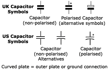
Capacitor
A Capacitor is an element which stores charge. It is comprised of two
conducting plates sepparated by a non-conducting material called a dielectric.
For every + unit charge put on one plate, there is an equal - unit charge on the
the other plate. Thus the entire capacitor is charge neutral. Since the + and - charges are
separated by a dielectric there is an electric field (or voltage) across the capacitor.

If positive charge is put on one plate then work is done because like-charges repel each other.Recall that voltage is related to work done on charge by the equation V=J/C.
The more charge on the capacitor's plates, the more work had to be done to put the charge there,
and the higher the voltage across the capacitor.
In this class all capacitors will be considered linear and will obey the following
charge-voltage relationship:
q = CV

The capacitor on the left is charging, therefore the voltage is increasing.
The capacitor on the right is actually discharging, therefore the voltage is decreasing.
Note the sign difference.
If voltage is not changing then dV/dt=0 and i=0. So in static (unchanging conditions)
the capacitor behaves like an 'open circuit' since no current flows.
Charge on a capacitor can not instantly leave. It takes some finite amount of time
for the charge to leave the plate. Therefore charge on the capacitor is continuous.
Since V = q/C then voltage across a capacitor is also continuous.
(i.e. The voltage across a capacitor can never change instantaneously.)
However the current can change instantaneously since i = C dV/dt.
This is because current is the rate of charge moving over time.
Energy stored in a capacitor is:
E = 1/2 CV2
A Capacitor is an element which stores charge. It is comprised of two
conducting plates sepparated by a non-conducting material called a dielectric.
For every + unit charge put on one plate, there is an equal - unit charge on the
the other plate. Thus the entire capacitor is charge neutral. Since the + and - charges are
separated by a dielectric there is an electric field (or voltage) across the capacitor.
If positive charge is put on one plate then work is done because like-charges repel each other.Recall that voltage is related to work done on charge by the equation V=J/C.
The more charge on the capacitor's plates, the more work had to be done to put the charge there,
and the higher the voltage across the capacitor.
In this class all capacitors will be considered linear and will obey the following
charge-voltage relationship:
q = CV
If this equation is differentiated we get:dq/dt = C(dV/dt)
or i = C(dV/dt)
The capacitor on the left is charging, therefore the voltage is increasing.
The capacitor on the right is actually discharging, therefore the voltage is decreasing.
Note the sign difference.
the capacitor behaves like an 'open circuit' since no current flows.
for the charge to leave the plate. Therefore charge on the capacitor is continuous.
Since V = q/C then voltage across a capacitor is also continuous.
(i.e. The voltage across a capacitor can never change instantaneously.)
However the current can change instantaneously since i = C dV/dt.
This is because current is the rate of charge moving over time.
Energy stored in a capacitor is:
E = 1/2 CV2
Using the above concepts, let's analyze the following circuit:
| This circuit has both a switch and a capacitor: The switch opens at t=0 The switch is closed for t<0 and is open for t>0. This can be seen by inspecting the switch's arrow direction. We will not try to analyze the circuit at t=0 since the circuit's state at t=0 is unkonwn. Instead we will look at the circuit at t=0- (the time right before the switch moves) and t=0+ (the time right after the switch moves). In this problem it is given that V4 = 8V at t=0-. With this information find the following things at t=0- and t=0+:
| |
| Here are snapshots of the circuit at t=0- and t=0+: _______________________________________________________ t = 0-:At t=0- the switch is closed. Since V4 = 8V andand the capacitor is in parallel with V4, then VC = 8V at t=0-. To determine i1 we need to find the voltage across the horizontal 4 ohm resistor. To find this, we will apply KVL: -20V + 4i1 + 8V = 0 4i1 = 20 - 8 = 12V i1 = 12/4 = 3A To find the current in the capacitor we have to apply KCL at the marked node: i1 = i + iC 3A = 2A + iC iC = 1A dV/dt = iC/C = 1A/(.25F) = 4V/s _______________________________________________________ t = 0+:At t=0+ the switch is open. Since the voltage across a capacitor can notchange instantly, then VC(0-) = VC(0+)Therefore VC(0+) = 8V Since the switch is now open no current flows through the horizontal resistor, so i1 = 0 To find the current in the capacitor we have to apply KCL at the marked node: i1 = i + iC 0A = 2A + iC iC = -2A dV/dt = iC/C = -2A/(.25F) = -8V/s dV/dt is negative, therefore for t>0 the capacitor is discharging. The energy stored in the capacitor is being absorbed by the resistor. Eventually all the initial energy stored in the capacitor will be absorbed by the resitor. |

No comments:
Post a Comment