Thursday, 7 November 2013

TUTORIAL- 1 - ENGLISH GRAMMAR

Grammar  rules  are  created  in  order  to  give  structure  to  the  language.  Rules  reflect  the  usual
behaviour  of  a  grammatically  constructed  pattern.  A  rule  does  not  necessarily  have  to  behave
absolutely the same every time, but will behave according to the rule  most of the time.

SENTENCE STRUCTURE

                       SUBJECT - VERB - COMPLIMENT - MODIFIER
                       Eg: MANU - WROTE - A STORY - LAST WEEK

Subject
  • The subject is the actor of a sentence in active voice. It is the person or thing that performs, or is responsible for, the action of the sentence. It usually begins the sentence and precedes the verb.
  •  Every sentence in English must have a subject. Commands will not have a visible subject, however, the subject [you] is understood. Example: Run quickly! = You run quickly!

The subject can be a single noun.
1. Cats chase mice.
2. Children  like candy.
The subject can also be a noun phrase, which is a group of words ending with a noun. A noun
phrase CANNOT begin with a preposition.

1. The car  is in the garage.
2. That hot red dress  looks fabulous.

Examples of subjects:
  1. Tom  likes to go fishing.
  2. The English teacher  is a very nice person.
  3. Susan and Alex went to the movie together.
  4. Those boys are good basketball players.
  5. We actors are a happy group.

Verb
  • The verb follows the subject when the sentence is declarative. A verb normally reveals the action of the sentence. Every sentence in English must have a verb.
  • The verb can be a single word.
  1. Mary likes chocolate cake.
  2. They play soccer.
  • The verb can also be a verb phrase. A verb phrase contains one, or more, auxiliary verbs and one main verb.
  • The main verb is always preceded by the auxiliary verbs.
  1. Martha has been talking to her new friend.
  2. Terry is visiting  his aunt today.
Examples of verbs and verb phrases:
  1. Jerry has returned from lunch.
  2. The storm made a lot of noise.
  3. George is playing  in a tournament tomorrow.
  4. I will go to bed soon.
  5. Sally was jealous of Lisa’s new dress.
Complement (Object)
  • A complement (object) provides more information about the verb. Often, it consists of a noun, or noun phrase, and will usually follow the verb in a sentence relaying active voice.
  • A complement (object) CANNOT begin with a preposition
  • A complement (object) answers the question what? or whom?
Examples of complements:
  1. Jack threw the stone far.        (What did Jack throw?)
  2. The hungry bird ate a worm.        (What did the bird eat?)
  3. He called Janice after the party.      (Whom did he call?)
  4. She was chewing gum  in class.      (What was she chewing?)
  5. The ball hit Mike during the game last night.  (Whom did the ball hit?)
Modifier
  • A modifier tells the time, place, or manner of action. The modifier usually follows the complement. Not every sentence requires a modifier.
  • Prepositional phrases are commonly used as modifiers
Examples of prepositional phrases:
under the house, after breakfast, in the morning
 
 
Adverbs and adverbial phrases are also used as modifiers, or modifiers of time. A modifier of
time will usually come last when more than one modifier is used.
 
Examples of adverbs and adverbial phrases:
yesterday, quickly,  last semester, overhead, quite awful
 
A modifier answers the question of where? When? or how?
 
Examples of modifiers:
  1. She is earning her degree at Cornell University.   (Where is she earning her degree?)
  2. John fell down the stairs        (Where did John fall?)
  3. yesterday.          (When did John fall?)
  4. The cheetah was running quite fast.      (How was the cheetah running?)
  5. We have an appointment at ten o’clock tomorrow.   (When do we have an appointment?)
  6. The soldier fired the gun repeatedly .       (How did the soldier fire the gun?)

Sunday, 14 July 2013

KAPERSKY PURE FULL VERSION 3 2013 EDITION [FREE GIVEAWAY FOR MEDIAONE USERS]


NOTE: THIS IS A FREE GIVEAWAY. PLEASE DONOT MISUSE THE OFFER
THIS GIVEAWAY IS A TOKEN OF APPRECIATION FOR MEDIAONE USERS

              New! Safe Money – adds more protection for financial transactions
  • Whenever you log onto an online shopping, banking or payment website, Kaspersky’s new Safe Money technology offers automatic protection. It checks the website’s URL against a list of secure sites, verifies the site’s security certificate and also scans your PC’s operating system to check for any related vulnerabilities. Safe Money also automatically suggests that the site is opened in the special Safe Money mode – to help further protect your personal data against theft.
    New! Secure Keyboard & improved Virtual Keyboard – help protect your identity
  • When you open a bank or payment website – or enter a password on a website – Kaspersky’s Secure Keyboard technology automatically prevents keyloggers from accessing the personal data that you type on your keyboard. Furthermore, Kaspersky’s improved Virtual Keyboard technology lets you input confidential data without even using a keyboard – so your information is safe from capture by ‘screen scrapers’, keyloggers and more.
  • New! Automatic Exploit Prevention – defends against the exploitation of vulnerabilities
    Malware is increasingly targeting vulnerabilities within commonly-used PC applications. Kaspersky PURE 3.0 Total Security includes a new technology – Automatic Exploit Prevention – that blocks malware from exploiting such vulnerabilities. Automatic Exploit Prevention scans your PC for vulnerabilities and controls the actions of any programs that have vulnerabilities. It blocks exploits by:
    • Controlling the launch of executable files by any applications that have vulnerabilities
    • Analysing the behaviour of executable files – to identify any similarities with known malicious programs
    • Restricting the actions that can be undertaken by applications that have vulnerabilities
  • New! Password Manager* now includes Password Sync
    Kaspersky’s Password Manager not only enhances your security – by generating secure, random passwords – it also automatically logs you onto your website accounts and applications, including Skype and Instant Messenger. Now, with the new Password Sync feature, Kaspersky PURE 3.0 securely stores your passwords online in the cloud. With Password Sync, you can safely access your passwords from any PC and be automatically logged onto your chosen websites and applications.
  • New! Online backup – makes data backup even more convenient
    If your PC fails, Kaspersky’s flexible backup features mean you can still access your documents, photos, music and other files. Kaspersky PURE 3.0 lets you backup your data onto your hard drive, removable media or a range of other physical storage. In addition, the new Online Backup feature allows you to store up to 2 GB of backup files online, via Dropbox – so you can use any PC with an Internet connection to access your backup.
  • Secure vaults – protect your most precious data
    With Kaspersky PURE 3.0, it’s easy to create a special, secure vault to store your most valuable information. Kaspersky encrypts all data that is stored in the vault and access to the vault is password-protected – to defend the vault against hacker attacks.
  • PC Cleanup tools – add security and help you preserve PC performance
    Easy-to-use PC Cleanup tools add to your security by letting you ‘shred’ deleted documents and delete your Internet browsing history. This helps to protect your privacy, prevent attacks by cybercriminals and keep your PC running more smoothly.
  • Home Network Control – simplifies management tasks across multiple PCs
    Kaspersky PURE 3.0 includes Home Network Control – to make it easy for you to launch scans, run updates, backup data and manage the security of multiple PCs on your home network – via a single PC.
  • Parental Control – helps to keep your children safe online
    Kaspersky PURE 3.0 makes it easy to monitor and limit your children’s online activities, communications and general PC usage. Convenient controls help you to protect your children from harmful Internet content or inappropriate websites, prevent downloads of specific types of files and also block communications with unwanted contacts via instant messaging or social networking.

    Click Here to Download the Software  [Note: You have to Skip ad 3 times

Saturday, 13 July 2013

TUTORIAL 4 - Kirchoff's Law Lab Practical

                                               Kirchoff's Law - Lab Practical
                   
                                    Note: You have to enable Java to use the Lab

Friday, 12 July 2013

TUTORIAL 3 - Thevenin Equivalent analysis with Practical Lab

This is a Lab Tutorial, So kindly use the Tool provided for better understanding

Note: Enable Java for using the Lab

Thevenin Equivalent


Here is a problem in which it's advantageous to use a Thevenin equivalent circuit. We want to determine the value of RL that will cause ib = 2 mA. (This is problem P5.5-12 from Introduction to Electric Circuits, 5e by R.C. Dorf and J.A. Svoboda.) We will solve this problem by finding a Thevenin or Norton equivalent circuit for the part of the circuit that is left of the terminals and then replacing that part of the circuit by its Thevenin or Norton equivalent circuit.
The row of buttons below the circuit correspond to various calculations that are used to find or to use a Thevenin or Norton equivalent circuit.
Thevenin and Norton equivalent circuits involve three parameters:
  • Voc, the open circuit voltage
  • Isc, the short circuit current
  • Rth, the Thevenin Resistance
The buttons labeled "Voc", "Isc" and "Rth" show how to find a Thevenin or Norton equivalent circuit for the part of the circuit that is left of the terminals:
  1. Left-click on the "Voc" button to see the circuit used to determine Voc, the open circuit voltage. The voltmeter measures the value of Voc in volts. Analyze this circuit, e.g. by writing and solving a mesh equation, to verify the value of Voc.
  2. Left-click on the "Isc" button to see the circuit used to determine Isc, the short circuit current. The ammeter measures the value of Isc in mA. Analyze this circuit, e.g. by writing and solving a mesh equation, to verify the value of Isc.
  3. Left-click on the "Rth" button to see the circuit used to determine Rth, the Thevenin Resistance. The current source causes the current in the equivalent resistance to be 1 mA. The voltmeter measures the value of the voltage across the equivalent resistance in volts. Thus
    Analyze this circuit, e.g. by writing and solving a mesh equation, to verify the value of Rth.
As expected (Section 5.5 of Introduction to Electric Circuits by RC Dorf and JA Svoboda), Voc, Isc and Rth are related by
Voc = Rth * Isc
The buttons labeled "Thevenin" and "Norton" show the circuits that result when the part of the circuit that is left of the terminals is replaced by its Thevenin or Norton equivalent circuit.
Left-click on the "Thevenin" button to see the circuit that we get when we use the Thevenin equivalent circuit. Analysis of this circuit shows
Next, left-click on the "Norton" button to see the circuit that we get when we use the Norton equivalent circuit. Analysis of this circuit shows
Of course, we expect both of these calculations to yield the same value of RL.
Finally, left-click on the "circuit" button to return to the original circuit. Verify that setting RL = 0 does indeed cause ib=2 mA.

Thursday, 11 July 2013

TUTORIAL 2 - Inductor

Inductor 


An inductor is an element which stores a magnetic field. An inductor is
a wire coiled around a material called a core. The core is typically made of 
a magnetic material however the core can be anything from a toilet paper roll to a piece of wood.

(The behavior of the inductor IS effected by the core material though.)

Recall from Physics that static charge sets up an electrostatic force. Also recall that
moving charge sets up a magnetic field called flux around the current-carrying wire.


If the wire is then coiled as shown below, then the flux increases linearly with every coil turn.


The flux is proportional to the current flowing through the inductor. 
We can use the following equation where L is the inductance of the inductor.(L is constant)

Flux = Li

Through experimentation it was found that if the flux changes then a voltage is induced.
If the flux is constant then there is no voltage across the inductor.

V = d(Flux)/dt
V = d(Li)/dt


V = L di/dt

When the current is changing a voltage is induced across the inductor.
This voltage opposes the change in the current.
When the current stops changing and stays constant, then the voltage collapses.
Therefore when conditions are constant (unchanging) the inductor appears like a
wire or short circuit.


Current is continuous in an inductor. In other words, current can not
change instantaneously. If current could change instantaneously then an infinite
voltage would be induced across the capacitor. Infinite voltage is a practical impossibility. 

Therefore current can not change instantaneously through an inductor.
Voltage across an inductor can change instantaneously.

The energy stored in an inductor is:

E = 1/2 Li2


Using the above concepts, let's analyze the following circuit:
This circuit has both a switch and an inductor:
The switch closes at t=0
The switch is open for t<0 and is closed for t>0.
This can be seen by inspecting the switch's arrow direction.
We will not try to analyze the circuit at t=0 since the circuit's
state at t=0 is unkonwn.
Instead we will look at the circuit at t=0- (the time right before
the switch moves) and t=0+ (the time right after the switch moves).

In this problem it is given that i6 at t=0- is 2A

With this information find the following things at t=0- and t=0+:
  1. The current through the inductor iL
  2. The current through the 6 ohm, i6
  3. diL/dt for the inductor
Here are snapshots of the circuit at t=0- and t=0+:
_______________________________________________________

t = 0-:

At t=0- the switch is open. Since we know that i6 is given to be 2A,
we can apply KCL to the marked node to find iL.
Σ  ientering = Σ  ileaving
5A = i6 + iL
5A = 2A + iL
iL = 3A at t=0-.

Now to find diL/dt:
diL/dt = VL/L
We need to find VL first:
Apply KVL to the right-most loop:
VL + 4iL - (2A)(6 Ohms) = 0
VL + 4(3A) - 12 = 0
VL = 12 - 12
VL = 0

diL/dt = VL/L = 0/2 = 0

_______________________________________________________

t = 0+:


iL(0-) = iL(0+)  This is always true!
Therefore iL(0+) = 3A
Current through an inductor is continuous 

We also need to fine i6:
Note that the 6 Ohm resistor has been shorted out by the closed switch.
A resistor in parallel with a wire has zero voltage across is.
If the 6 Ohm resistor has zero volts across it then the current
through the 6 Ohm has to be zero due to Ohm's Law, V=IR.
Thus i6(0+) = 0

Now to find diL/dt:
diL(0+)/dt = VL(0+)/L
We need to find VL(0+) first:
VL + 4iL - 0 = 0
VL + 4(3A) = 0
VL = -12

diL/dt = VL/L = -12/2 = -6A/s


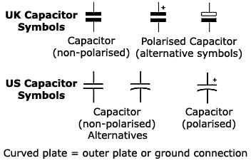
TUTORIAL 1 - Capacitor

Capacitor


A Capacitor is an element which stores charge. It is comprised of two
conducting plates sepparated by a non-conducting material called a dielectric.

For every + unit charge put on one plate, there is an equal - unit charge on the
the other plate. Thus the entire capacitor is charge neutral. Since the + and - charges are
separated by a dielectric there is an electric field (or voltage) across the capacitor.


If positive charge is put on one plate then work is done because like-charges repel each other.Recall that voltage is related to work done on charge by the equation V=J/C.

The more charge on the capacitor's plates, the more work had to be done to put the charge there,
and the higher the voltage across the capacitor.


In this class all capacitors will be considered linear and will obey the following
charge-voltage relationship:

q = CV
If this equation is differentiated we get:dq/dt = C(dV/dt)

or      i = C(dV/dt)


The capacitor on the left is charging, therefore the voltage is increasing.
The capacitor on the right is actually discharging, therefore the voltage is decreasing.
Note the sign difference.


If voltage is not changing then dV/dt=0 and i=0. So in static (unchanging conditions) 
the capacitor behaves like an 'open circuit' since no current flows.

Charge on a capacitor can not instantly leave. It takes some finite amount of time
for the charge to leave the plate. Therefore charge on the capacitor is continuous.
Since V = q/C then voltage across a capacitor is also continuous.
(i.e. The voltage across a capacitor can never change instantaneously.)

However the current can change instantaneously since i = C dV/dt.
This is because current is the rate of charge moving over time.

Energy stored in a capacitor is:
E = 1/2 CV2


Using the above concepts, let's analyze the following circuit:

This circuit has both a switch and a capacitor:
The switch opens at t=0
The switch is closed for t<0 and is open for t>0.
This can be seen by inspecting the switch's arrow direction.
We will not try to analyze the circuit at t=0 since the circuit's
state at t=0 is unkonwn.
Instead we will look at the circuit at t=0- (the time right before
the switch moves) and t=0+ (the time right after the switch moves).

In this problem it is given that V4 = 8V at t=0-. 

With this information find the following things at t=0- and t=0+:
  1. The voltage across the capacitor.
  2. The current i1
  3. The current in the capacitor (going down)
  4. dV/dt in the capacitor
Here are snapshots of the circuit at t=0- and t=0+:
_______________________________________________________

t = 0-:

At t=0- the switch is closed. Since V4 = 8V and 
and the capacitor is in parallel with V4, then VC = 8V at t=0-.

To determine i1 we need to find the voltage across the
horizontal 4 ohm resistor. To find this, we will apply KVL:
-20V + 4i1 + 8V = 0
4i1 = 20 - 8 = 12V
i1 = 12/4 = 3A

To find the current in the capacitor we have to apply KCL at the marked node:
i1 = i + iC
3A = 2A + iC
iC = 1A

dV/dt = iC/C = 1A/(.25F) = 4V/s
_______________________________________________________

t = 0+:

At t=0+ the switch is open. Since the voltage across a capacitor can not
change instantly, then VC(0-) = VC(0+)Therefore VC(0+) = 8V

Since the switch is now open no current flows through the horizontal resistor,
so i1 = 0

To find the current in the capacitor we have to apply KCL at the marked node:
i1 = i + iC
0A = 2A + iC
iC = -2A

dV/dt = iC/C = -2A/(.25F) = -8V/s

dV/dt is negative, therefore for t>0 the capacitor is discharging.
The energy stored in the capacitor is being absorbed by the resistor.
Eventually all the initial energy stored in the capacitor will be absorbed
by the resitor.

Wednesday, 10 July 2013

PIC MICROCONTROLLER AND EMBEDDED SYSTEMS - M.A.MAZIDI


PIC Microcontroller and Embedded Systems offers a systematic approach to PIC programming and interfacing using the Assembly and C languages. Offering numerous examples and a step-by-step approach, it covers both the Assembly and C programming languages and devotes separate chapters to interfacing with peripherals such as timers, LCDs, serial ports, interrupts, motors and more. A unique chapter on the hardware design of the PIC system and the PIC trainer round out coverage, while text appendices and online support make it easy to use in the lab and classroom.

Features
  • Systematic coverage of the PIC18 family of microcontrollers.
  • Coverage of C language programming of the PIC18-starting from Chapter 7.
  • Chapters (9-17) on programming and interfacing the PIC with peripherals.
  • An entire chapter (Chapter 8) dedicated to the design of the PIC Trainer.

Table Of Contents

  • The PIC Microcontrollers: History and Features
  • PIC Architecture & Assembly Language Programming
  • Branch, Call, and Time Delay Loop
  • PIC I/O Port Programming
  • Arithmetic, Logic Instructions, and Programs
  • Bank Switching, Table Processing, Macros, and Modules
  • PIC Programming in C
  • PIC18F Hardware Connection and ROM Loaders
  • PIC18 Timer Programming in Assembly and C
  • PIC18 Serial Port Programming in Assembly and C
  • Interrupt Programming in Assembly and C
  • LCD and Keyboard Interfacing
  • ADC, DAC, and Sensor Interfacing
  • CCP and ECCP Programming
  • Radio wave Propagation
  • SPI Protocol and DS1306 RTC Interfacing
  • Motor Control: Relay, PWM, DC, and Stepper Motors 
 Click here to download the Book